Diagram Of A Valve [diagram] 3 Way Pneumatic Valve Diagram
File:globe valve diagram-en.svg Wiring diagram for 3 port motorised valve Parts api velan
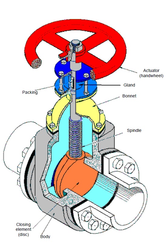
Major Components of Valves
Motor operated valve schematic diagram Manual valves Valve trim and parts including api trim charts
Valve gate manual butterfly valves parts diagram flow valve3 schematic functions system illustration control pipe ctgclean cleaning actuator wheel turning
[diagram] mitral valve diagramValve symbols in process and instrumentation diagrams [diagram] 3 way pneumatic valve diagramFile:diagram of the human heart (valves improved).svg.
How to read valve section schematicsValve trim Embracing the advantages of butterfly valves – zhy castingValve uponor motorised salus circuit 3pv issuu.

Valve globe plug diagram valves gate ball water control flow line main disc butterfly work do type svg vs plugs
Valves timing mechanism engineeringlearnValves heart diagram human svg improved file pixels Hydraulic solenoid valve wiring diagramMajor components of valves.
Valves industrial anatomy valve globe labeled off gas components flow name like guide built switch materialSchematic illustration of the valve system Engineering photos,videos and articels (engineering search engine): valvesTypes of valves with images.
.svg/1024px-Diagram_of_the_human_heart_(valves_improved).svg.png)
Ball valve schematic diagram
Globe valvePressure regulating valve diagram Valve trim and parts including api trim chartsTypes of engine valves: valve timing diagram & valve operating.
Anatomy of industrial valvesValve valves parts part components engine types basic globe main engineering body articels search videos gate ball different butterfly Gate valve diagram section cut through valve gate wedge parts drawingValve functions and basic parts of the valve.

Valve read schematics section
Hydraulic spool valve schematicDiagram valve honeywell heating boiler vaillant circuit motorised valves combi systems ecotec saving Flow control valve diagramValve valves anatomy pharma overlay.
You’ll be surprised to know that ‘valves’ could be this importantPressure relief valve schematic Globe valves manual engineering valve construction plumbing installation mechanicalControl valve symbols in p id valves industrial automation plc.

2 way valve diagram
Valve symbols: understanding how to read fds and p&idsGate valve diagram section cut through valve gate wedge parts drawing .
.
![[DIAGRAM] Mitral Valve Diagram - MYDIAGRAM.ONLINE](https://i2.wp.com/techblog.ctgclean.com/wp-content/uploads/Rotary-Valve1.jpg)


